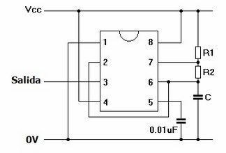
Circuito 555 Astable
Since the discharge pin is off, current can flow through resistors R1 and R2, charging capacitor C1. Once C1 charges to 2/3 Vcc, the output is switched off by the threshold pin. When the output goes off, the discharge pin switches on. This allows the charge accumulated on capacitor C1 to drain to ground. Once the voltage across C1 drops to 1/3 Vcc, the trigger pin turns off the discharge pin, so C1 can start charging again. A Blinking LED Circuit To observe the 555 timer in astable mode, let's build a circuit that uses the 555 timer's oscillating output to make an LED flash on and off: R1: 4. 7K Ohm resistor R2: 4. 7K Ohm resistor R3: 1K Ohm resistor C1: 100 μF capacitor The values of R1, R2, and C1 affect the speed of the blinking. Larger values will make the LED blink slower, while smaller values will make the LED blink faster. Resistor R3 is just there to limit the current to the LED so it doesn't burn out. If you want to set the blinking to a certain speed, you can use the formula at the beginning of this article to calculate the resistance or capacitance you need.
555 Timer Basics - Astable Mode

Bistable Mode (or Schmitt Trigger) A Bistable Mode or what is sometimes called a Schmitt Trigger, has two stable states, high and low. Taking the Trigger input low makes the output of the circuit go into the high state. Taking the Reset input low makes the output of the circuit go into the low state. This type of circuit is ideal for use in an automated model railway system where the train is required to run back and forth over the same piece of track. A push button (or reed switch with a magnet on the underside of the train) would be placed at each end of the track so that when one is hit by the train, it will either trigger or reset the bistable. The output of the 555 would control a DPDT relay which would be wired as a reversing switch to reverse the direction of current to the track, thereby reversing the direction of the train. Prev Page: Inside the 555
CLICK HERE FOR INDEX PAGE THE 555 ASTABLE CIRCUIT IN DETAIL V. Ryan � 2002 - 2017 Electronic timers are central to school projects. You will find as you develop your circuits that the timer circuit can be adapted to suit many purposes. There are several reliable timers but the 555 timer is the most common. Whether you are putting together an alarm or a circuit to activate a computer, a timer is the common component. The 555 timer IC (integrated circuit) is very stable, relatively cheap and reliable. It may be used as monostable or astable. Astable means that the 555 can operate repeatedly, it will switch on, then off, then on, then off, continually. The 555 is sometimes called an oscillator. Below is a typical 555 astable circuit that drives an LED. It is known as a LED flasher as the LED flashes on and off. The number of flashes per minute can be altered by turning the variable resistor. Remember the 555 is activated by current at pin two and the output is through pin three. Altering the variable resistor alters the time between �pulses� at pin three.

Circuito 555 astable industrial
This takes some amount of time determined by R2 and C1. Once again C1 is discharging from 2/3Vcc to 1/3Vcc so the time will be 0. 693(R2C1). Here's an actual scope trace of the threshold (green) and output (yellow) pins. This circuit is called astable because it doesn't have a stable state that it needs to be bumped out of like the monostable. Rather, it's continuously alternating between charging C1 from 1/3Vcc to 2/3Vcc and discharging it back to 1/3Vcc. The output is correspondingly high while C1 charges and low while it discharges. The time the output is high is 0. 693(R1+R2)C1. The time the output is low 0. 693(R2)C1. The total cycle time is the sum of these: 0. 693C1(R1+2R2). This means that the frequency is the reciprocal of that: 1. 44/((R1+2R2)C1). Because the charge time depends on R1+R2 and the discharge depends on R2, the two times can not be equal, so you can't get a 50% duty cycle. This, however is seldom a real issue. In those cases where it is, you can achieve it by doing some tricks using the CMOS version of the 555.
- Astable Operation | Getting to know the 555 | Adafruit Learning System
- 555 astable
- 555 timer astable oscillator
- Articulos de bebe en uruguay
- 555 (NE555) Astable Circuit Calculator
This guide was first published on Mar 13, 2018. It was last updated on Mar 13, 2018. This page (Astable Operation) was last updated on Nov 06, 2020.
Home 555 Astable Circuit Calculator The 555 timer is capable of being used in astable and monostable circuits. In an astable circuit, the output voltage alternates between VCC and 0 volts on a continual basis. By selecting values for R1, R2 and C we can determine the period/frequency and the duty cycle. The period is the length of time it takes for the on/off cyle to repeat itself, whilst the duty cycle is the percentage of time the output is on. ie. T 1 /T. In this type of circuit, the duty cycle can never be 50% or lower.